CANADIAN RESEARCH – Modular Assembly
Off-site construction distinguishes itself from traditional construction by offering shorter project timelines and potentially reduced costs. Furthermore, prefabricating some or all components inside a factory, allows not only to spend less time on the construction site, but also tends to improve the quality of buildings. Elements are built under controlled conditions, sheltered from the vagaries of weather, and where quality control can be performed more easily.
This type of construction would however benefit from a more efficient assembly solution to facilitate and accelerate the installation of the prefabricated elements on site, especially when it comes to large buildings. To address this challenge, Laurence Picard undertook a Ph.D. in mechanical engineering within the Industrialized Construction Initiative at Laval University, in Quebec City, under the supervision of Pierre Blanchet and André Bégin-Drolet. The objective of her project? To develop a self-locking connector to quickly connect prefabricated modules together on the building site, to optimize the benefits of prefabrication, especially for multi-story light-frame modular construction.
Today, when such prefabricated modules are erected on site, workers must perform certain manual operations to secure the hardware required to assemble the prefabricated elements. In addition to the time required to perform for this step, it also necessitates leaving certain areas of the modules accessible, i.e. unfinished, to carry out these interventions. This research project was therefore launched with the aim of optimizing this stage by developing a device to speed up the fastening of prefabricated elements together.
An exhaustive list of functional and technical design specifications has been established by the project team. Among these, the locking mechanism had to be automated, had to follow a vertical movement and the device had to be easily manufactured in a factory. There had to be a visual or sound confirmation of the connection, while unlocking of the connecting device had to be possible and performed in less than 3 min. Furthermore, the connecting device had to be located inside the walls and floors to allow for module completion, also the building’s vertical-compressive load paths could not be affected by the connector. Finally, the tensile capacity had to be at least 200 kN, while the compressive capacity had to be at least 1000 kN and the shear capacity had to be at least 40 kN. These design requirements acted as guidelines for the connector’s iterative design process. Computer-aided designs were generated, and digital simulations were performed during the design iteration process. Parts were then 3D printed for functionality testing, and finally prototypes were manufactured for experimental testing; steps that allowed to select the final design.
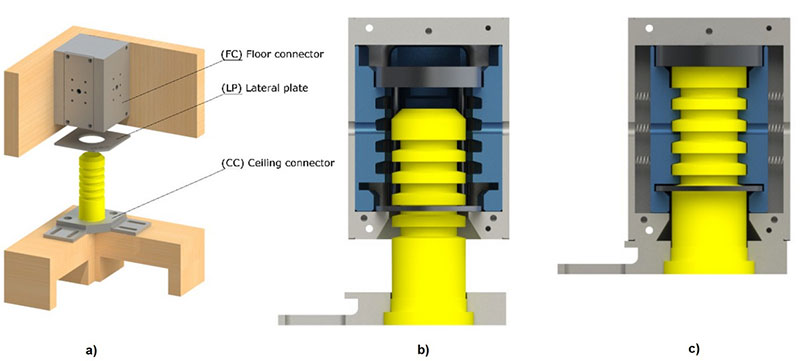
This design process led to the development of a self-locking connector consisting of two main elements, the floor connector and the ceiling connector. The first one, attached to the main floor beams, comprises the automatic locking box. The second, attached to the ceiling beam, comprises a shaft which rises upwards. When assembling the modules, as the upper module descends onto the lower module, the shaft is guided into the cylindrical cavity of the floor connector. When the shaft strikes the release block at the bottom end of the hole, the latch mechanism is deployed, and the connection completed (Figure 1).

Figure 1 Overview of the developed connector a) its main components b) the connection in process and c) in its final locked position (Source: Laurence Picard)
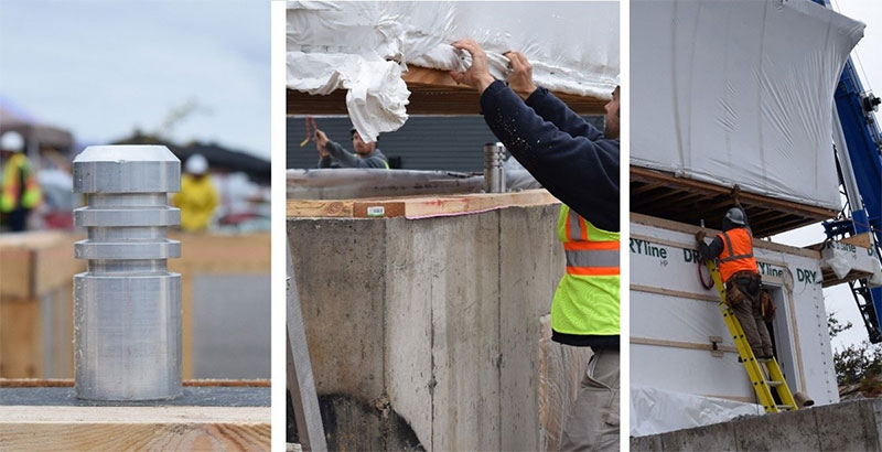
Once the development was completed, and before being able to use these connectors on real size buildings, they have been tested in the lab to evaluate their tensile, compressive and shear capacities, as the connectors support these types of loads in a building and contributes to the building’s load path. Connectors have shown sufficient performance in the lab to allow further development. They were then tested in operation, on steel jigs in the lab, and finally a full-scale implementation was performed on a real building. A total of twelve connectors were tested in a two-story house comprising four modules and a concrete basement (Figure 2).

Figure 2 Images of the large-scale test carried out with the connector on a two-story house (photo credit: Circerb)
This full-scale experiment allowed to evaluate the connector efficiency and its impact prior and during the installation of the modules on site. Overall, the experiment led to promising results, the connector offered a simple means of efficiently connecting modules together at the construction site. However, as expected, further refinement of the connector and its installation is required to optimize its use and take better advantage of the time savings it can offer. Regarding the design requirements that needed to be encountered by the device, observations during on-site implementation led to several conclusions. Among the characteristics that were judged to be satisfactory, first the parallelism of the module with the ground was attainable and adequate to avoid interference during descent. The module flexibility was sufficient to compensate differences between ceiling and floor dimensions, leading to a smooth shaft insertion for all twelve connectors. The conic surface of the connectors allowed to guide the descent and positioning of the module for an easier and accurate connection process. Moreover, the lifting movements did not impact the module interior finish, i.e. no finish defects were observed inside the modules after installation.
On the other side, some challenges were observed on site, regarding the success of the connections and the sound indication, confirming the connections. The analysis of cameras footage and the visual observations of the workers confirmed that the shafts of the ceiling connector did enter smoothly in the floor connector for all twelve ACDs. However, the connection was incomplete for most connectors (2/12). This was attributed to missing vertical displacement leading to an incomplete shaft insertion in the connector and therefore impartial engagement of the grippers. These placement problems can be explained by the fact that the positioning prescribed in the production plans for the installation did not consider unpredictable dimensional variations caused by moisture content and creep when the modules were stored outside on trestles for a long period. We can expect that on a regular project, with a higher control of these elements, the dimensional changes would be less of a problem, leading to a higher rate of connection. Moreover, according to the scientific literature, the risk associated to incomplete connections is limited regarding the structural behaviour of the building, for instance during a seism. In other words, even if the connection is incomplete, the connector fulfils its role in connecting the modules, ensuring most of its structural functions.
Regarding the time saved using connectors on site, it was difficult to evaluate in this context of innovation. First, when implementing new practices, the novelty of the project contributes to longer realization times. Moreover, since it was carried out as part of a scientific study, many measurements and observations had to be done by the research team, thus slowing down operations. But because of their quick automated connection and because of the higher level of completion they allow, it is expected that they will allow to greatly reduce the building erection time when they become commonly used in prefab modular projects. However, in this full-scale project, because of the novelty of their use, their installation on the modules at the prefabrication plant took a considerable amount of time. It requires an extensive dimensional control for the accurate positioning of ceiling and floor connectors, so that the two parts can precisely be inserted into each other on site. It can be anticipated that the time required to install them in the plant will decrease with experience and with the development of more automated installation techniques.

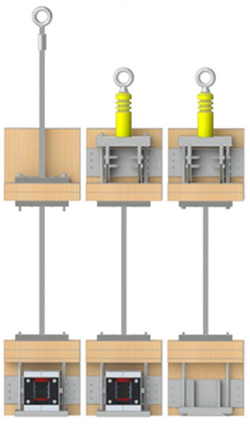
Figure 3 Possible configurations for the automated connecting and lifting device (Source: Laurence Picard)
The use of the developed connectors as attachment points for modular handling and lifting was also investigated during this full-scale experiment to evaluate the pros and cons of combining connecting and lifting functions in a single device. Handling the modules on site presents its technical challenge, the assembly process must adhere to a safe and efficient lifting procedure, ensuring minimal deformation of the lifted module to preserve both its structural integrity and its aesthetics. Consequently, for the developed connector to have a lifting function as well, new pieces, such as lifting rods, eyebolt and plates, were added to the connector design (Figure 3).
Their use in this two-story residential home allowed to evaluate their performance in application. Beneficial and challenging elements have been identified. A first challenge was encounter when positioning these devices within the structure. Traditionally, temporary lifting threaded rods are installed at the plant, during the module manufacture, but once the module in place on site, they are un-screwed and removed from the structure. Therefore, their positioning is not critical. In the case of the permanent rods developed in this project, their presence has led to considerable constraints in the architectural and structural design because these lifting rods had to be hidden in the wall.
Once this positioning challenge was overcome, they did perform well on site. Researchers considered that the lifting activities were successful, while the workers did appreciate using this new method. Lifting by four eyebolts has proven to be very efficient and appreciated by the workers who considered that it is an easier attaching option, compared to traditional practices.
Nevertheless, because of their restrictive impact on the building design, because of the lower-than-expected time savings allowed by their use, compared to the traditional lifting method, and because of their higher prices since they cannot be reused in other projects just like traditional rods, the researchers concluded that this specific design is not recommended for future projects. Future research and development work could however optimize the device’s design to improve their balance sheet.
Conclusion
In summary, this research project led to the development of an innovant and promising connecting device for light frame modular buildings. As for any technology in development, work still needs to be done in order to optimize its use for the prefabrication industry. But it offers several advantages that motivate further development. The developed automated connector can boost efficiency increasing the module level of completion, reducing manual labor and potentially assembly time, while ensuring precise connections between modular elements. It however necessitates an initial investment and introduces complexities in dimensional control during off-site installation. Moreover, on-site perturbations, like fluctuations in moisture content and storage conditions, can affect the success rate of the connections. The industry will need to adapt its practices for the effective adoption of the connection, particularly for the dimensional control of modules.
Combining the connecting and lifting functions in a single device on its side led to the conclusion that the device should be mainly used for its connecting function. The connector itself has a limited impact on the architecture of the buildings as they are hidden in the flooring and ceiling systems with other mechanical components such as HVAC, electrical and plumbing elements. Conversely, implementing the lifting axes induced many additional design constraints in the project that impacted the feasibility of some floor layouts.
A patent has been obtained for the connector developed. It has been licensed for commercial use by a company.
Source: Canadian Architect


Leave a Reply
Want to join the discussion?Feel free to contribute!